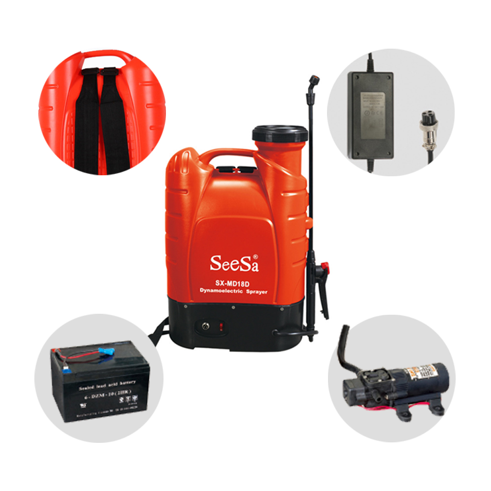
Squeezing the trigger on your application equipment should deliver a consistent, reliable mist. Instead, operators frequently face sudden pressure drops, erratic spray patterns, or a pump that continuously cycles on and off. These operational frustrations disrupt agricultural, pest control, and landscaping applications, wasting time and expensive chemical formulations. Misunderstanding the internal mechanics—specifically how the pump, pressure switch, and trigger valve interact—leads to misdiagnosed equipment failures, unnecessary replacement costs, and inefficient chemical application. You might replace a perfectly good motor when a simple seal is at fault, extending equipment downtime. Understanding the fluid dynamics and electrical feedback loop of a knapsack electric pressure sprayer is required for troubleshooting existing units, evaluating new models for purchase, and ensuring long-term equipment reliability from the moment of unboxing.
Demand-Driven Mechanics: Electric knapsack sprayers utilize a pressure-sensitive micro-switch that activates the pump only when line pressure drops (trigger open) and cuts power when pressure peaks (trigger closed).
Component Vulnerability: The most common causes of pressure failure in standard 4-gallon units are worn check valves, degraded O-rings, and fouled pressure switches, rather than total motor failure.
Setup and Calibration: Proper initial setup—specifically matching the correct nozzle to the pump's output—is critical to preventing rapid pump cycling and premature controller burnout.
Evaluation Criteria: When shortlisting a knapsack sprayer, prioritize units with accessible, user-serviceable pump assemblies and adjustable pressure regulators to match varying flow rates.
The Anatomy of a Knapsack Electric Pressure Sprayer
Diagnosing pressure irregularities requires mapping the internal components that generate and regulate fluid flow. The system relies on a precise sequence of mechanical and electrical interactions. When these components function correctly, chemical application remains predictable across the entire job site. Field technicians must understand each part of this assembly to isolate faults quickly without tearing down the entire machine.
The Diaphragm Pump and Motor Assembly
The core power plant of commercial units consists of a 12V DC motor mated to a diaphragm pump head. The motor converts battery power into rotational energy. An internal eccentric cam bearing translates this rotation into a rapid push-pull linear motion. This mechanical action drives a flexible diaphragm back and forth inside the pump chamber at high speeds.
During the backward stroke, the diaphragm creates a vacuum. This suction pulls fluid from the main tank, past the intake check valve, and into the pump chamber. During the forward stroke, the diaphragm compresses the fluid. The intake valve snaps shut, and the exhaust valve opens, pushing the pressurized liquid into the delivery hose. The primary advantage of this design is isolation. The diaphragm moves the fluid without the harsh agricultural chemicals ever touching the internal metallic motor components. This physical separation prevents rapid corrosion from fertilizers, herbicides, and bleach solutions.
Manufacturers typically use chemical-resistant materials for these internal components. Diaphragms are often molded from Santoprene for flexibility and fatigue resistance, while the check valves utilize Viton or similar synthetic rubbers to withstand solvent-based chemicals. Understanding these material specifications helps operators choose the right equipment for specific chemical applications.
The Pressure Switch (Demand Switch) Mechanism
Located directly on the pump head, the internal pressure switch serves as the brain of the operation. It acts as a mechanical-to-electrical bridge, translating fluid dynamics into electrical commands. Inside this small housing, a tiny trigger mechanism holds back a heavy-duty spring. This spring rests against a secondary, smaller diaphragm exposed directly to the fluid line.
The electrical contacts inside the switch are normally closed (NC). When hydraulic pressure in the delivery hose shifts, it pushes against this internal switch diaphragm. If the fluid pressure is high, it overcomes the spring tension, pushing the mechanism backward to snap the electrical contacts open. This breaks the positive electrical circuit and stops the motor instantly. When line pressure drops, the spring forces the mechanism forward, snapping the contacts closed with precision. This instant electrical connection restores power to the motor.
This micro-switch endures significant physical and electrical stress. Every time the contacts open or close, a small electrical arc occurs. Over thousands of cycles, this arcing can cause carbon buildup on the contact points, eventually leading to electrical failure even if the mechanical spring remains intact.
The Trigger Valve and Fluid Line
The fluid pathway begins at the bottom of the tank, travels through a suction filter, enters the pump chamber, and exits into the high-pressure delivery hose. This pathway terminates at the trigger valve located on the wand handle. The trigger valve is not just an ergonomic handle; it is a mechanical barrier that dictates the entire operation of the machine.
When you release the handle, the internal plunger drops and seals the valve seat. Because the pump has already pushed fluid into the hose, closing this barrier creates a pressurized, static fluid column. This static pressure is absolutely required for the system to function. It travels backward through the hose to push against the pressure switch at the pump head, signaling the system to shut down.
The integrity of this fluid line is non-negotiable. A loose hose clamp, a cracked wand tube, or a worn O-ring inside the trigger handle will bleed off this static pressure. If the pressure bleeds off, the switch will not register a closed trigger, and the pump will continue to run or cycle erratically.
The Physics of the Trigger: Opening and Closing the Valve
The operational rhythm of a knapsack sprayer depends entirely on the physics of hydraulic pressure. The system constantly seeks equilibrium between the physical fluid restriction at the wand and the electrical power driving the pump. Operators who understand this relationship can easily calibrate their equipment for optimal performance.
What Happens When the Trigger Opens (Pressure Drop)
Squeezing the trigger handle lifts the internal plunger away from the valve seat. This action immediately releases the static fluid pressure trapped in the hose. The pressurized liquid rushes out through the wand and nozzle, atomizing into a spray pattern based on the nozzle's orifice design.
This physical release triggers a rapid sequence of events inside the machine:
The static line pressure drops instantly as fluid escapes the nozzle.
Back at the pump head, the powerful spring inside the pressure switch decompresses because the opposing hydraulic force is gone.
The spring pushes the internal mechanism forward.
The electrical contacts snap closed, completing the circuit.
The motor receives 12 volts of direct current and spins up to operating RPM.
The pump begins cycling fluid, drawing from the tank and pushing it out the wand to maintain a continuous spray.
What Happens When the Trigger Closes (Backpressure Build-Up)
Releasing the trigger initiates an equally rapid shutdown sequence. The plunger drops back onto the valve seat, abruptly stopping all fluid flow at the wand. However, the motor is still spinning at high RPMs. The pump continues to push fluid into the closed hose for a fraction of a second.
Because liquids are largely incompressible, forcing more fluid into a sealed space causes the line pressure to spike rapidly. This intense backpressure travels down the hose to the pump head. It pushes hard against the pressure switch diaphragm. This hydraulic force overcomes the physical tension of the internal spring. The mechanism shifts backward, breaking the electrical circuit. The motor loses power and halts instantly, leaving the system primed and pressurized for the next squeeze.
This sudden stop creates a minor water hammer effect. You can often feel a slight kick or vibration in the hose when the trigger closes. High-quality sprayers use reinforced braided hoses to absorb this shock and prevent the fittings from blowing off under peak pressure.
The Phenomenon of Pump Cycling (Stuttering)
Operators frequently encounter a frustrating issue where the pump rapidly turns on and off—stuttering or pulsing—while the trigger is fully open. This is not a motor failure. It is a mismatch between fluid output and physical restriction.
This cycling occurs when the pump's flow rate significantly exceeds the nozzle's output capacity. The pump pushes fluid into the hose faster than the small nozzle orifice can release it. This causes micro-spikes in line pressure. These spikes trick the pressure switch into thinking the trigger is closed, shutting the motor off momentarily. Once the motor stops, the nozzle releases the excess pressure, the switch closes, and the motor restarts. This rapid on-off cycle degrades the micro-switch contacts over time and creates an uneven spray pattern.
Many users experience this immediately after unboxing. If you install a low-flow restriction nozzle for fine misting without adjusting the pump's pressure regulator or variable speed dial, the system will inevitably stutter. Proper calibration between pump speed and nozzle size is required to achieve a smooth, continuous motor run.
Nozzle Type
Flow Rate (GPM)
Required Pump Setting
Symptom if Mismatched
Fine Mist Cone
0.1 - 0.2
Low / Minimum
Severe rapid stuttering; pump cycles multiple times per second.
Standard Fan
0.3 - 0.5
Medium
Occasional pulsing; uneven spray distribution at the edges.
Adjustable Brass (Open)
0.6 - 0.8
High / Maximum
Smooth operation; pressure may drop if pump cannot keep up.
High-Volume Drench
1.0+
Maximum
Continuous run; weak pressure if nozzle exceeds pump capacity.
Common Causes of Inconsistent Pressure in a Knapsack Sprayer
When equipment fails in the field, operators often assume the motor has burned out. Total motor failure rarely happens. Inconsistent pressure usually stems from degraded seals, electrical continuity issues, or power supply drops. Diagnosing these specific components saves time and repair costs.
Faulty Pressure Switches and Electrical Relays
The micro-switch endures thousands of physical snaps and electrical arcs during a single workday. Over time, mechanical wear weakens the internal spring. If chemical leaks occur near the pump head, corrosion can degrade the electrical contacts. This causes the switch to stick permanently in either the "on" or "off" position.
To execute a basic repair approach, you must isolate the pump controller. Follow these diagnostic steps in the field:
Disconnect the battery completely to ensure safety.
Remove the bottom plastic pump cover to access the switch housing on the pump head.
Set a digital multimeter to the continuity or Ohms setting.
Probe the two electrical terminals on the micro-switch.
Manually depress the switch diaphragm with a small screwdriver.
You should hear a clear beep from the multimeter when the switch closes, and silence when it opens. If the multimeter registers continuity regardless of switch position, the internal contacts have welded together.
Running a unit with welded contacts presents a severe implementation risk. A stuck switch causes the pump to run continuously against a closed trigger. The pump will build maximum deadhead pressure until something fails. This can blow a delivery hose off its barb, rupture the pump head, or cause the motor to overheat and melt the surrounding plastic housing.
Worn O-Rings, Seals, and Check Valves
Internal check valves are small rubber or silicone discs that maintain one-way fluid flow. They sit over the intake and exhaust ports of the pump chamber. When the diaphragm moves, these valves open and close rapidly to pull fluid in and push it out, holding pressure within the system.
In standard 4-gallon battery backpack sprayers, sudden pressure loss often stems directly from debris or harsh chemicals degrading these seals. If you mix wettable powders improperly, abrasive particles can score the valve seats. Solvent-based chemicals can cause the rubber to swell or deform. If a check valve cannot seal completely, fluid pushes backward into the tank during the compression stroke. This is known as internal bypass.
When internal bypass occurs, you will hear the pump running normally, but high pressure fails to build at the wand. The spray pattern will look weak and anemic. Inspecting and cleaning these tiny valves often restores full pressure immediately. Field technicians should always carry a spare set of check valves and O-rings for quick swaps.
Battery Voltage Drop Under Load
Electrical power dictates mechanical output. A depleted or failing lithium-ion or lead-acid battery may show a full charge on a basic indicator light but fail to provide sufficient amperage under a heavy load. When the pump attempts to build high pressure, it draws maximum current.
If the battery cells are degraded, the voltage drops significantly the moment the motor demands power. The motor spins slower, the diaphragm strokes lose their force, and the resulting spray pattern becomes weak. You might assume the pump is failing because the switch functions and the valves are clean. Testing the battery voltage with a multimeter while the pump is actively running under load will reveal if the power source is the true bottleneck.
Battery Type
Resting Voltage
Voltage Under Load (Healthy)
Voltage Under Load (Failing)
12V Sealed Lead-Acid
12.6V - 12.8V
11.5V - 12.0V
Drops below 10.5V
18V/20V Lithium-Ion
20.0V - 20.5V
18.0V - 19.5V
Drops below 15.0V
Evaluating Knapsack Sprayers: Features That Prevent Pressure Failure
Selecting the right equipment requires looking past marketing claims and examining the internal engineering. The longevity of a sprayer depends on how well it manages pressure, handles abrasive chemicals, and allows for field maintenance. Operators must evaluate specific mechanical features before committing to a purchase.
Variable Pressure Controls vs. Single-Speed Pumps
Standard on/off demand pumps operate at a single speed. When the switch closes, the motor runs at maximum RPMs until the pressure limit is reached. This binary operation is harsh on the internal components and often leads to the stuttering phenomenon if the nozzle is too small. The constant starting and stopping generates excess heat and wears out the motor brushes prematurely.
Models featuring variable rheostat dials offer a superior solution. A variable flow control dial uses pulse-width modulation (PWM) to regulate the voltage sent to the motor, allowing the operator to adjust the pump's RPMs. You can dial down the motor speed to perfectly match the output of a low-flow nozzle. This eliminates rapid cycling, prevents stuttering, and significantly extends the life of the pressure switch and motor.
Pump Quality: Diaphragm vs. Piston Mechanisms
Evaluating pump mechanisms requires understanding the mechanical differences between diaphragm and piston designs. Diaphragm pumps utilize a flexible membrane to move fluid. Because there are no sliding friction parts in contact with the chemical, they are highly resistant to abrasive wear. They are the superior choice for applying wettable powders, suspended solids, and harsh bleach solutions.
Piston pumps operate like a combustion engine cylinder. A piston slides up and down inside a sleeve to build pressure. They can achieve significantly higher maximum pressure ratings, making them excellent for reaching high tree canopies or spraying thick liquids. However, the sliding friction requires strict maintenance. Abrasive powders will quickly score the cylinder walls and ruin the O-rings, leading to permanent pressure loss. Choose the pump type based strictly on the chemical formulations you intend to spray.
Serviceability and Replacement Part Availability
Equipment will eventually require maintenance. Smart purchasing decisions heavily emphasize serviceability. Avoid units with sealed, glued, or proprietary pump housings that cannot be opened with standard hand tools. If you cannot access the pump head in the field, the machine is a liability.
Prioritize purchasing from brands that offer modular replacement parts. You should be able to buy standalone pressure switches, check valve kits, and replacement diaphragms. If a minor seal fails or a controller malfunctions, replacing a small, inexpensive part gets you back to work in minutes. Requiring a full pump and motor replacement for a degraded O-ring is an unacceptable maintenance burden for commercial operators.
Conclusion
Inspect your inline suction filters and clean them thoroughly before assuming a weak spray pattern is caused by motor failure.
Calibrate your variable pressure dial to match your chosen nozzle orifice to eliminate rapid pump stuttering and protect the micro-switch.
Keep a modular rebuild kit containing spare check valves, O-rings, and a replacement pressure switch in your field maintenance vehicle.
Flush the pump system with clean water after every use to prevent harsh chemicals from degrading the internal diaphragm and seals.
FAQ
Q: Why does my electric knapsack sprayer keep running when the trigger is closed?
A: This indicates an inability to build sufficient backpressure to trigger the shutoff switch. Common causes include an internal fluid leak, debris stuck in the check valve preventing pressure build-up, or a welded pressure switch mechanism physically stuck in the closed electrical position.
Q: Why is my 4-gallon battery backpack sprayer losing pressure while spraying?
A: Pressure loss during active spraying usually stems from a clogged suction filter restricting fluid intake, worn pump diaphragm or check valves causing internal bypass, or a dropping battery voltage that can no longer sustain the motor load required to push high pressure.
Q: How does the pressure switch on a knapsack sprayer work?
A: It uses a tiny trigger mechanism and a powerful spring that monitors hose pressure. When line pressure is low, the spring pushes forward, snapping the electrical contacts closed to run the pump. When pressure spikes, it overcomes the spring, snapping the contacts open to stop the motor.
Q: Why does my sprayer pump pulse or stutter rapidly right out of the box?
A: The installed nozzle orifice is too small for the pump's current output setting. The pump pushes fluid faster than the nozzle can release it, causing rapid pressure spikes that trigger the auto-shutoff repeatedly. Adjust the variable pressure dial down or install a larger nozzle.
Q: Can I repair the pump controller on a knapsack electric pressure sprayer?
A: Yes, most commercial units allow for step-by-step replacement of the internal components. You can access the pump head to replace the pressure switch, diaphragm, and check valves using standard rebuild kits without needing to replace the entire motor assembly.
Q: What is the difference between a demand pump and a bypass pump in sprayers?
A: Demand pumps shut off entirely when the trigger closes, relying on a pressure switch to break the electrical circuit. Bypass pumps continue running even when the trigger is closed; they route pressurized fluid internally back into the tank to maintain system pressure without stalling the motor.
Shixia Holding Co., Ltd. was establishes in 1978, that has more than 1,300 employees and more than 500 sets of various injection molding machines, blow molding machines and other advanced equipment.